There has been quite a bit of information released about The Wizard of Oz regarding its overall design, fit and finish, gameplay (yes, there are videos out there), and rules. I figured I would delve inside the machine and look at some of the engineering and parts used.
 I received my Wizard of Oz pinball machine on May 17th. I was a day one order and as best as I can figure my machine is pretty early in the production schedule. The production date on the serial number sticker is 5/1/2013 (May 1).
The game shipped with a manual that is incomplete. An updated and downloadable copy is supposed to be available very soon now available. Still, I have to give props to JJP for including a printed manual. In looking through the manual it further dawns on you how much work went into this game to get it from an idea to a fully working pinball machine in 2 years and 5 months. There are tons of game specific parts that had to be designed, prototyped, tested, and produced.
Anyway, on to the pictures and guts of the game. When removing the glass, there is an important warning on top of the coin door:
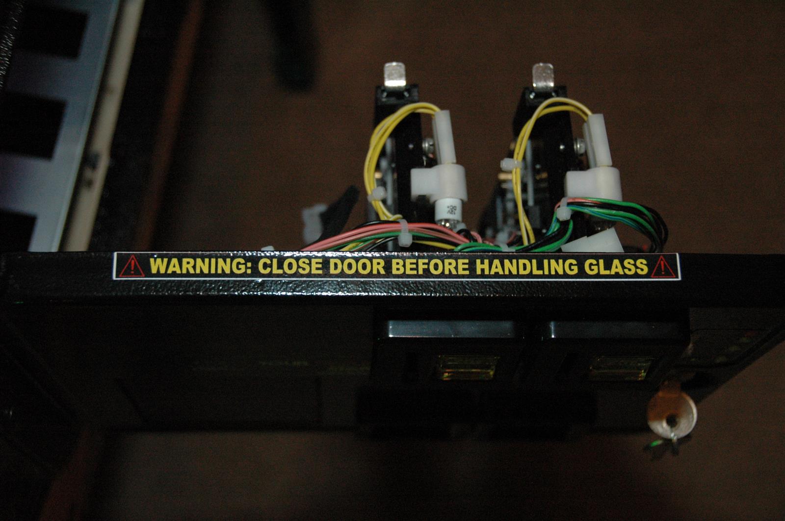 Make sure you close the coin door before you remove the glass. If you don’t, you run the risk of putting a nice long scratch in the underside of the Invisiglass.
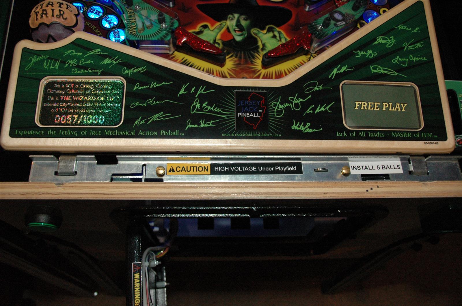
Upon removing the lockdown bar, you are greeted with a familiar sight:
 JJP claims the coin door was a new design to incorporate the Pinnovators headphone audio board. It is different than Happ coin doors on new Stern games. In addition to the audio controls, it has no raised portion in the middle and it will only accept an upstacker bill validator.
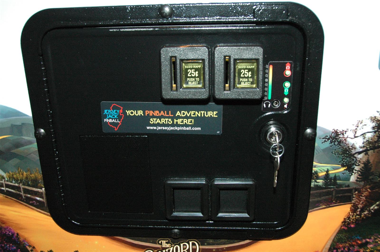
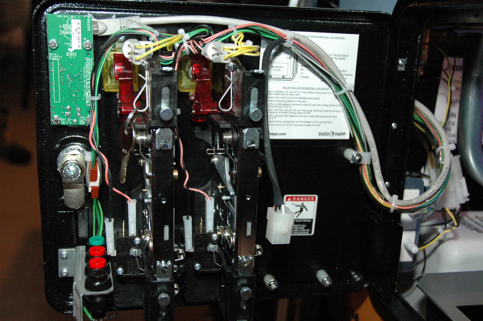
Here’s the inside of the coin door showing the Pinnovators board. The menu buttons are the familiar 4 button arrangement of Back, -, +, and Enter.
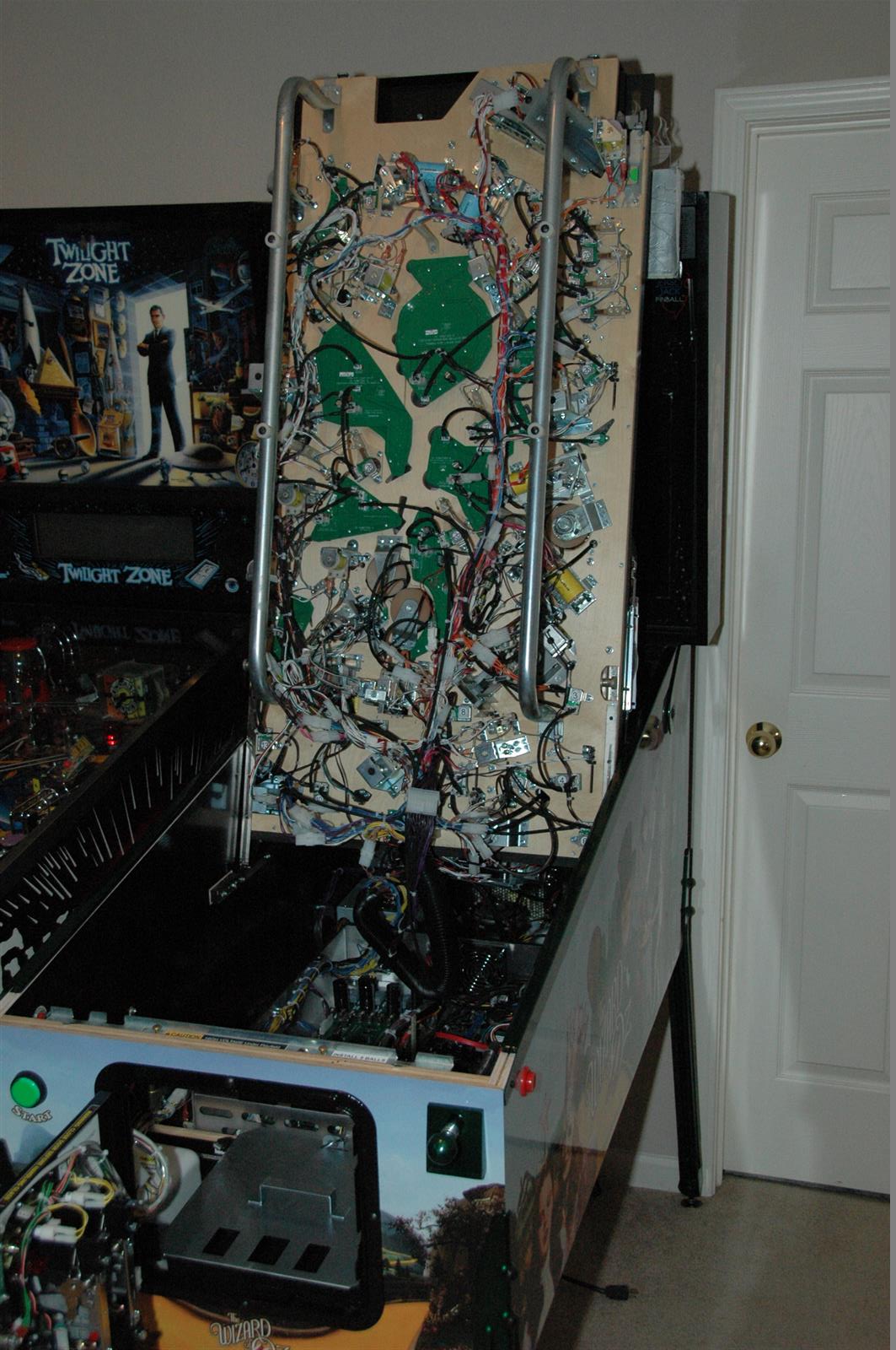
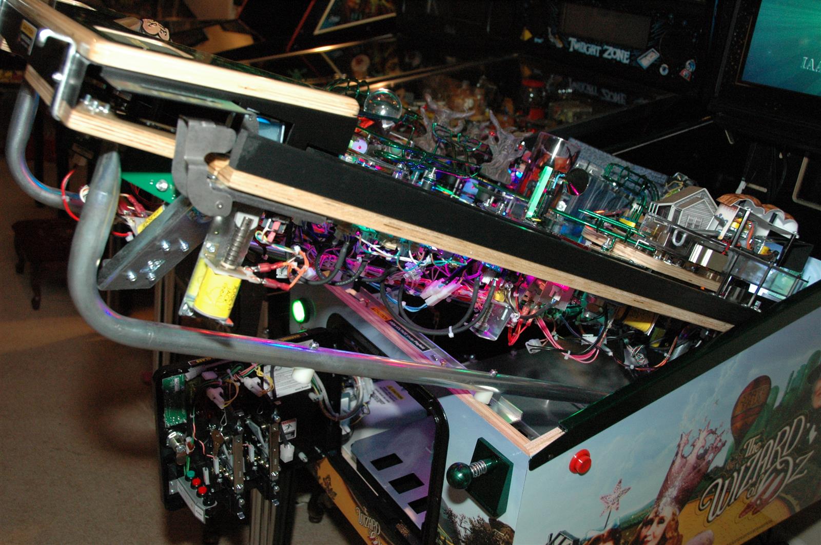
The playfield rails are great and the playfield props up in a couple different positions. You can easily reach everything under the playfield and inside the cabinet, front and back. Here the playfield is propped in its most outward position before lifting.
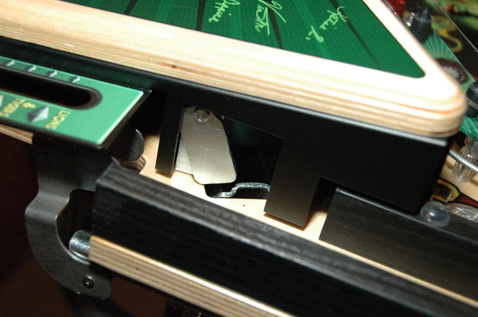
 A nice touch is the ball retainer for the trough as seen on Pin2k games of the past. It works well and you don’t have to remove the balls when raising the playfield. I’ve had a ball fall out once, and that was probably due to me not being careful.
 At the front of the cabinet we have the shaker motor and USB connector that is used for updates. The connector is at the upper right corner of the shaker motor.
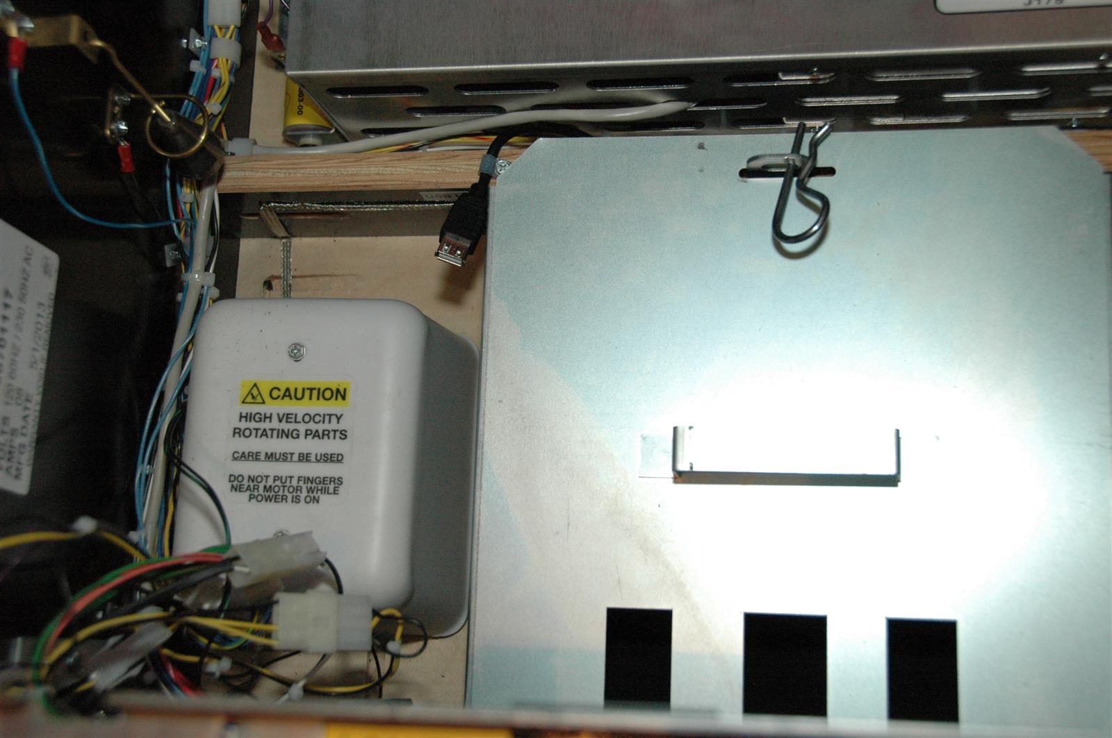
I have updated my game’s sofware to version 1.08. You need a USB thumb drive of at least 8 GB. The update process involves downloading an iso file, extracting it to the USB drive, plugging the drive into the connector, then turning the game on. Pretty easy. Version 1.08 is a full code update. It has been explained that once a stable code base is reached, rules updates will be much smaller and quicker to apply.
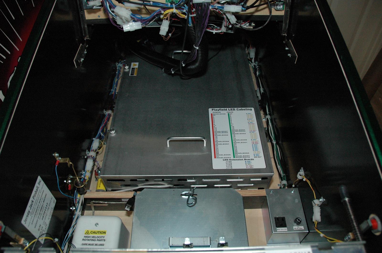 Here’s a shot of the cabinet bottom, from the front. The aluminum PCB chassis assembly (term used in the JJP manual) is the dominant feature:
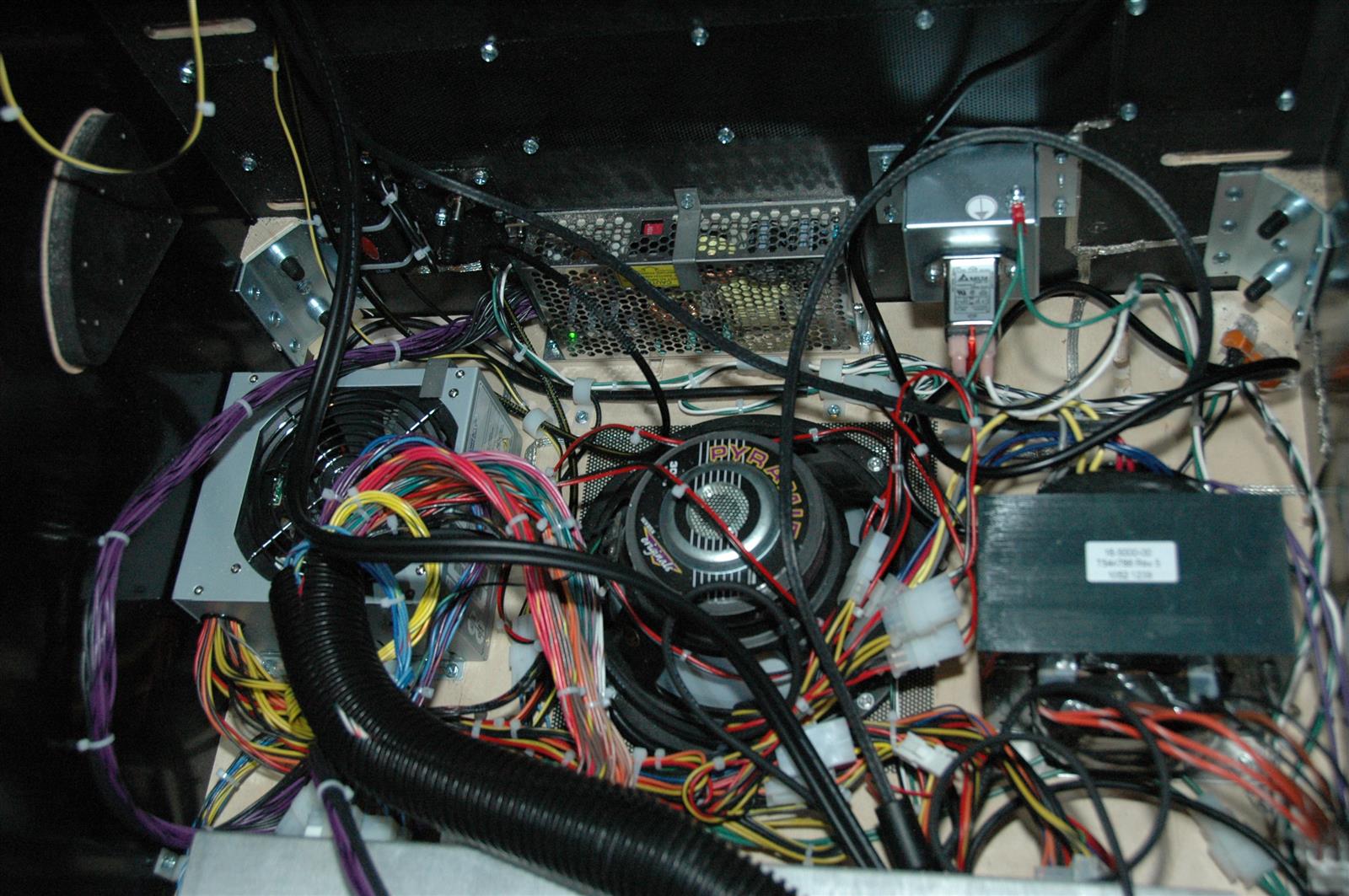
The back side of the cabinet showing the ATX power supply, another power supply, cabinet speaker, transformer, audio filter, and tons of wiring.
 Seen below, all the playfield wiring runs to the back of the PCB chassis. It is easily disconnected, but there is a lot of it. On my game there is one board under the playfield that has wiring that does not run through the disconnects at the back of the cabinet. If the playfield were removed, this single wire would have to be disconnected from the driver board and pulled through the back. I imagine this will be corrected in later versions of the game.
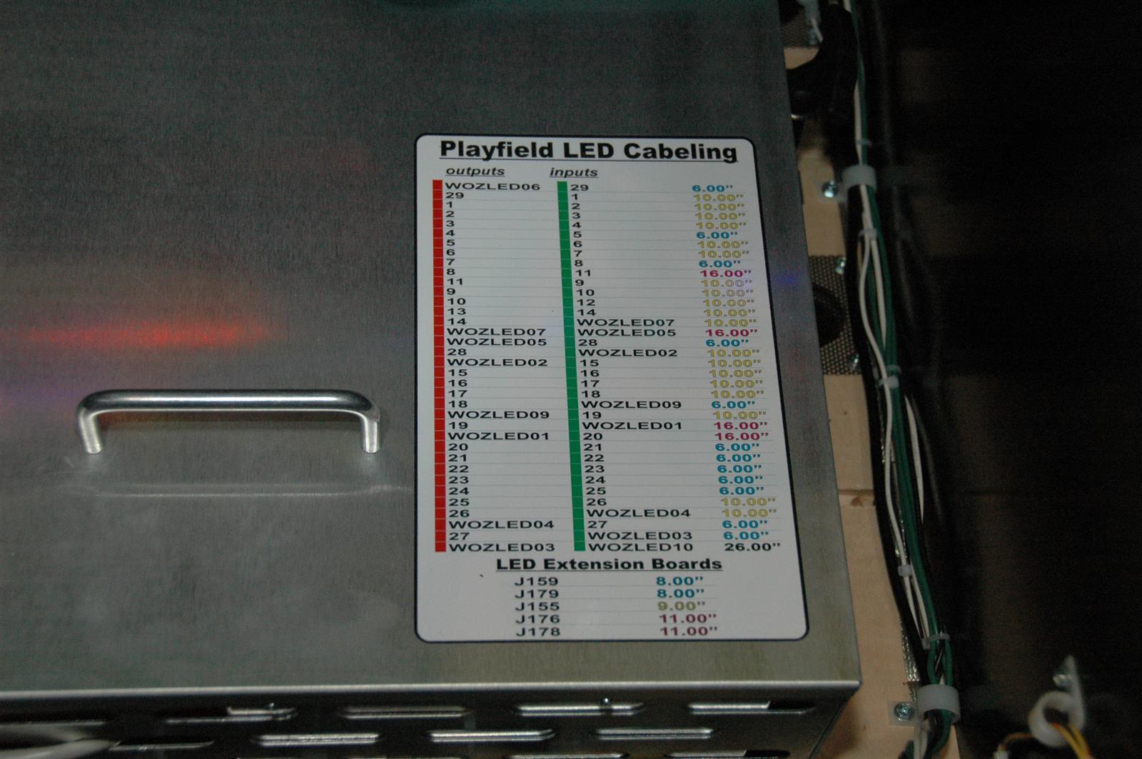
 On the front corner of the PCB chassis there is a sticker which has the routing information for the RGB LED data cables. The boards are serial, which I believe is similar to the setup Stern uses for their color changing LEDs. More on that later.
Below is the knocker assembly:
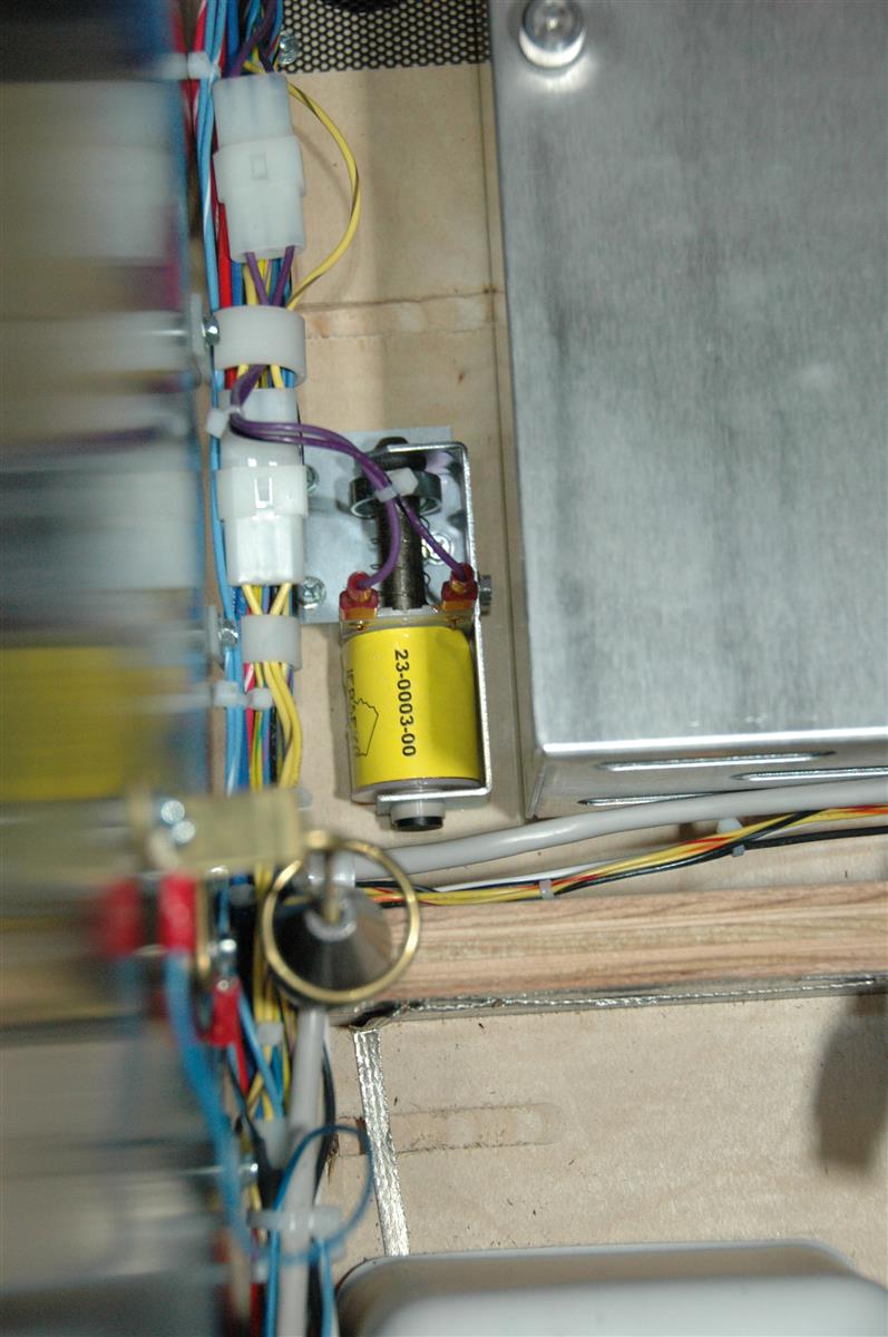 There’s not much in this game that is a disappointment. Unfortunately the knocker is one of the few things that disappoints. It is mounted like the Data East and Sega knockers that strike the cabinet brace across the bottom. So right off the bat the knock is muted due to the knocker’s location and where it strikes. The next disappointment is that it is a 20v coil. So it is further neutered by the low voltage coil. I have visions of re-mounting it so that it strikes on the cabinet side. That should help. But it still won’t have the thwack of the backbox mounted 50v knockers that were in Williams/Bally games of the past. All that being said, at least it is a real knocker.
Update: Supposedly there will be a service update released that will address the knocker. I’ll update this post when more information is available.
I’m going to stop here for Part 1. We’ve gotten you inside the game and looked at some of the major features. I will probably have additions and updates in the future. In Part 2 and Part 3 I’ll look under the playfield and at the electronics inside the PCB chassis.