The capacitor located at C1 on the strobe power supply board for Attack From Mars (AFM) is notorious for failing. Bally/Williams used a 100v non-polar capacitor in a location that has at least 140v across it all the time. Finding a replacement non-polar electrolytic capacitor with a voltage rating of greater than 100v proved difficult. Actually, you can find them, but they are usually so large they will not fit within the strobe’s power supply box. So I decided to take matters into my own hands.

Update: Pinsider yonkiman researched and detailed an alternate way to fix this issue. It is simple and involves only a diode (and a new capacitor, of course). His write up for the fix can be found here. His analysis of the circuit and the fix can be found here. When I perform this fix in the future I’m going to use his method detailed in the links above.
In short, his method is to install a diode to prevent negative voltage across the capacitor during power up. Purchase an axial 100uF 250v polarized electrolytic capacitor (voltage can be greater than 250v if desired). On the back of the strobe board install a 1N4004 diode across the capacitor’s leads. In the photo below the diode that needs to be installed for C1 is on the left near the circular black stamp marking. Note the polarity of the diode. Make sure the banded side of the diode is oriented in the right direction.
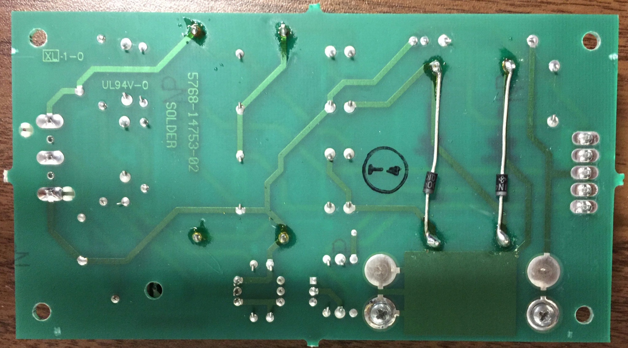
Photo courtesy yonkiman.
The other diode on the right is for C2. This can also be installed but it isn’t necessary to fix the inherent design problem with C1. I recommend installing it. Won’t hurt anything, can only help.
Onward to my original way of fixing the failed capacitor:
The strobe in my AFM was working, but I was having the playfield restored and doing a restoration on the machine, so I figured I may as well check the condition of C1 and replace it if necessary. In the photo above, you can see C1 is bulging at the top (black capacitor on the left). After I removed it, it measured 68 µF, so it was definitely on the way out.
A non-polarized electrolytic capacitor is basically two polarized capacitors that are wired in series. You can effectively make a non-polarized capacitor by wiring two capacitors in series with the same leads connected. I.e. positive to positive or negative to negative. Keep in mind that when capacitors are wired in series, the total capacitance is a reciprocal of each individual capacitor’s capacitance. So two 200 µF capacitors in series will give you a total capacitance of 100 µF. However, when wired in series the voltage capacity of capacitors adds (*I’ve found some debate about whether the voltage adds, it may not) . So two 100v capacitors in series effectively gives you a capacitor rated at at least 200v.
I had on hand two 220 µF, 200v polarized capacitors. By hooking them in series, I ended up with the equivalent of a 110 µF capacitor with a voltage tolerance of at least 200v. The extra 10 µF above the initial 100 µF value of C1 is not a concern.
Here’s what I used:
")
Here’s the end result, wired in series and ready for installation. They are held securely together with hot melt glue:
")
And below is the repair installed and ready for installation in the game. The capacitors fit inside the strobe’s power supply box with room to spare. I used some hot melt glue to make sure they are firmly secured to the circuit board. My game is back together and I’m happy to report that this repair works fine and should last a long time.")