Part 1 of my write up got you inside the game and around the inside of the cabinet. We’ll now look under the playfield, inside the backbox, and at some of the assemblies.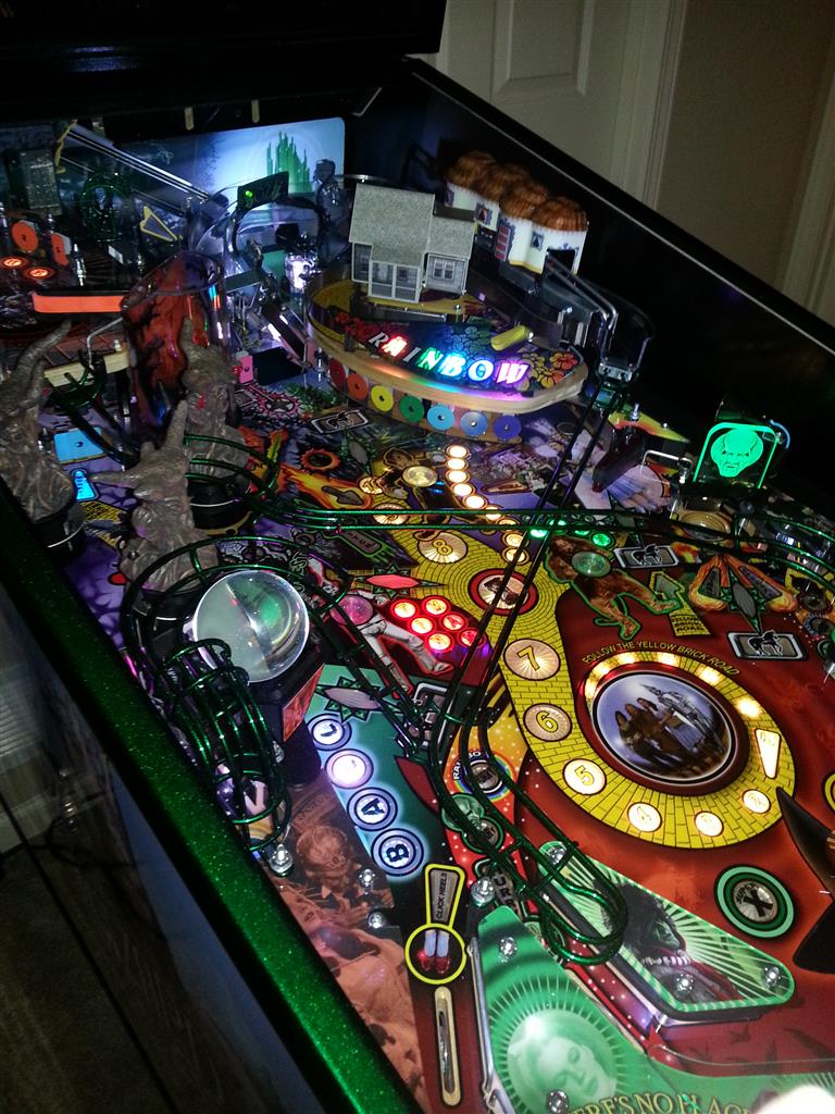
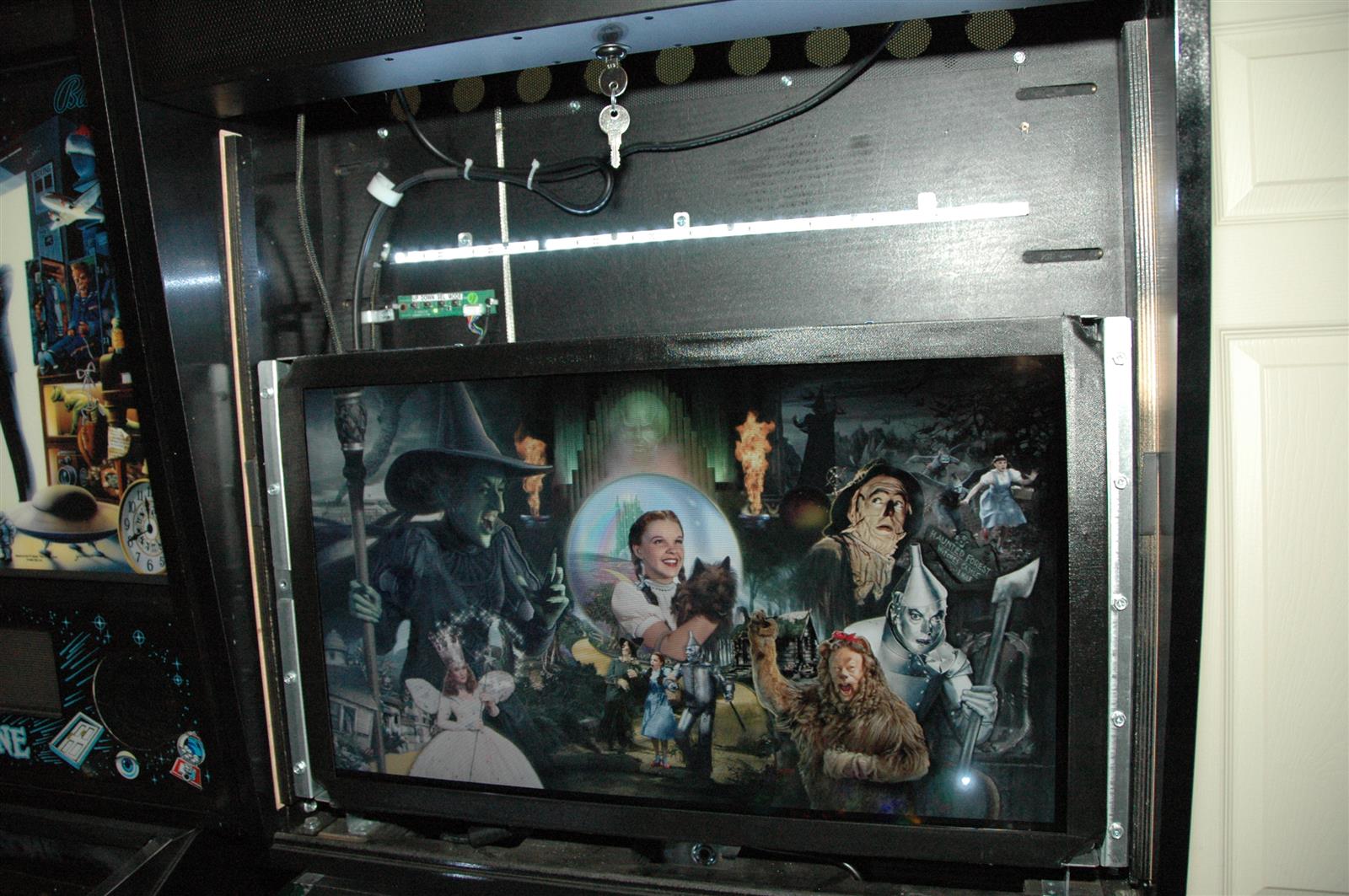
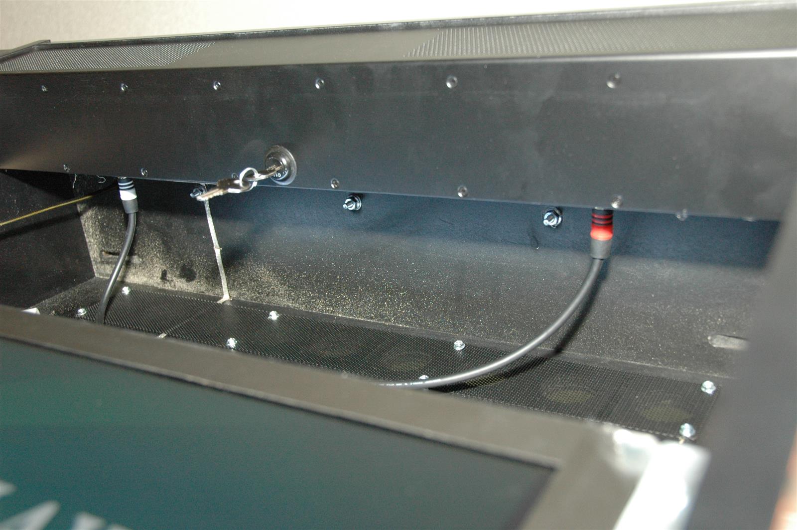
First off we have what may be the most boring backbox since Iron Man Classic. Since the guts of the game are in the cabinet, the only thing in the backbox is the 26″ LCD, the LED strip for backglass illumination, the menu buttons for the LCD, and some wiring for the speakers and topper.
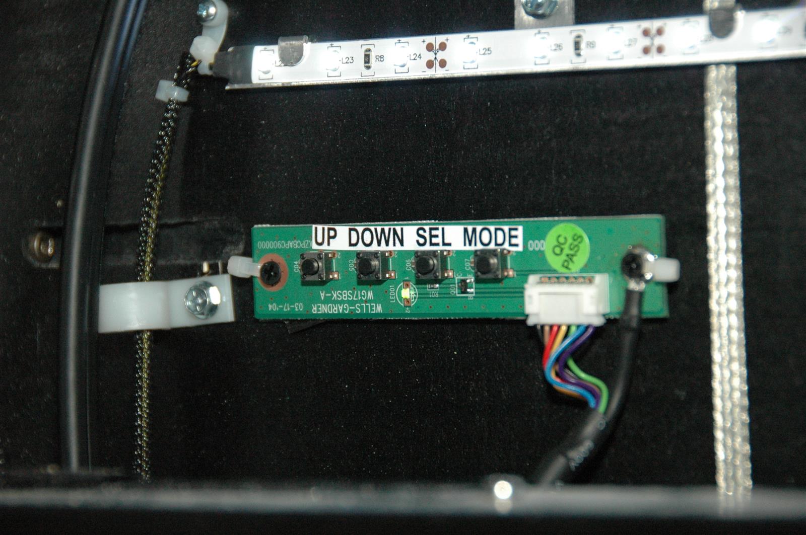
 Below are the menu buttons for the LCD:
 And the wiring for the six speakers and topper:
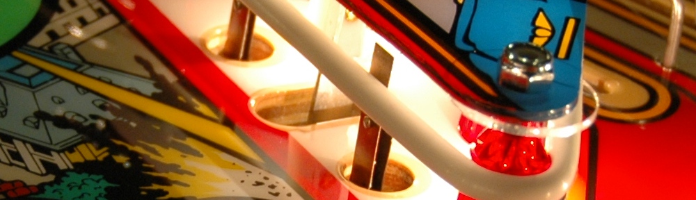
 Okay, it gets better after this. One thing to note is that the flipper lugs are wired differently than WMS flippers. They work the same, the wiring is just connected to different lugs. The different placement of the diodes shows this:
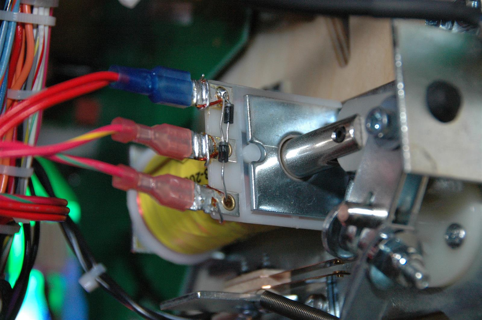 While we are on the flippers, it is nice to see the familiar pawl assemblies that Pinball Life sells which you can loosen and tighten with only a 3/8″ wrench. No having to mess with an Allen key to tighten and adjust flippers.
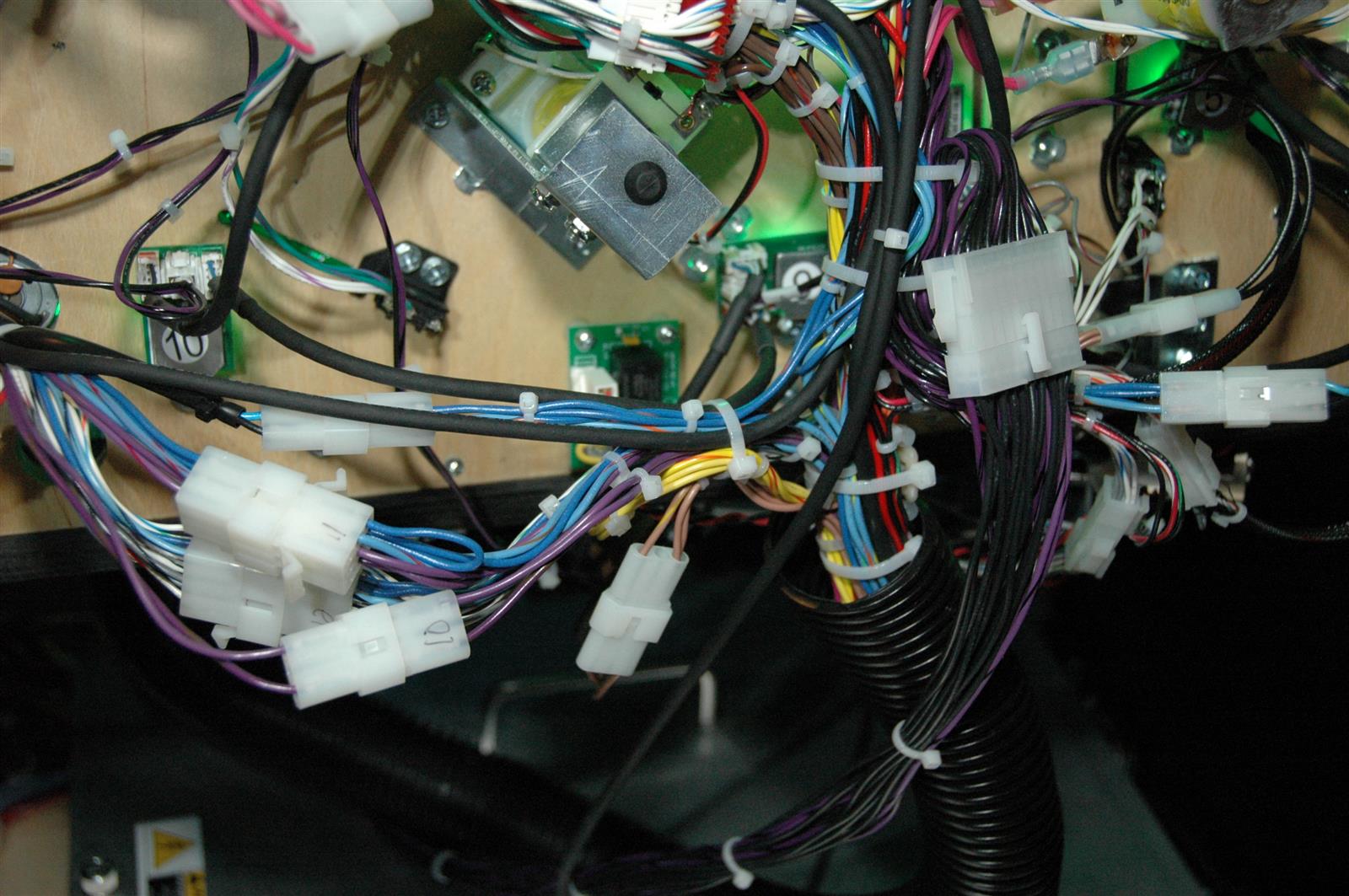
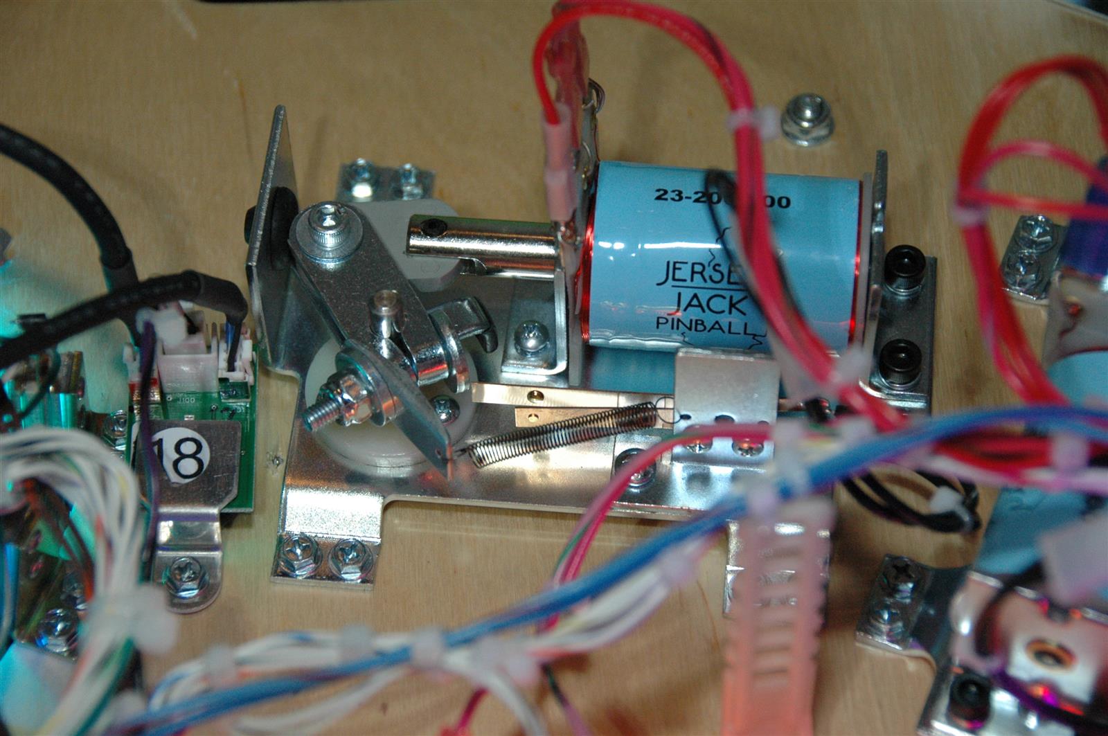 Pretty much everything under the playfield has its own connector. In fact, everything probably does, I haven’t looked at every single item. So disassembly and maintenance should be fairly easy. Below is the back of the playfield:
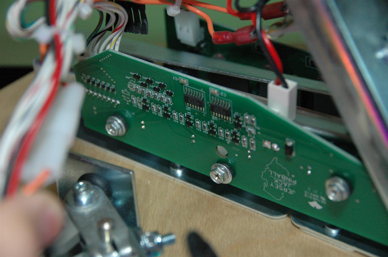
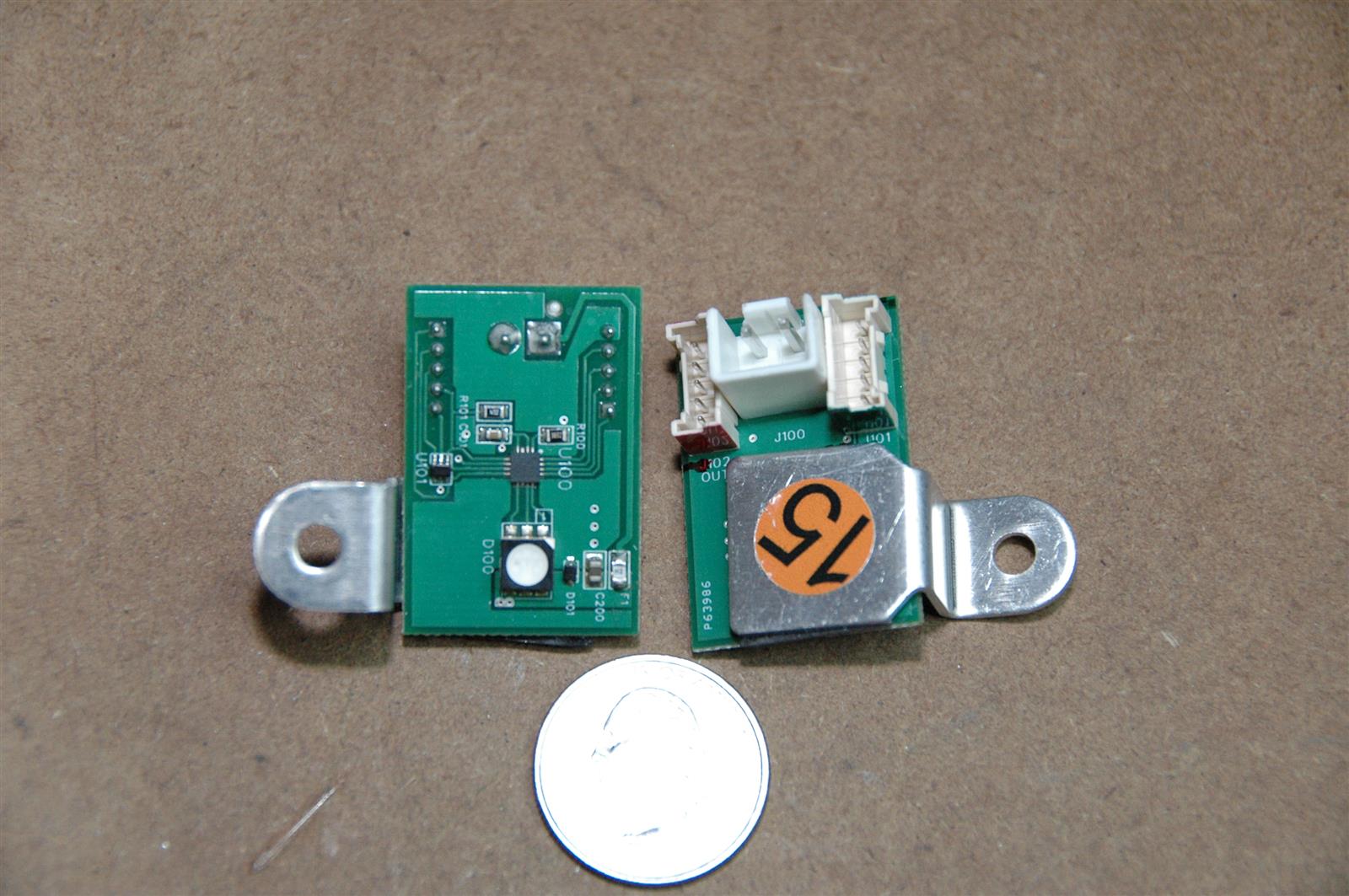
 The ball trough uses the familiar optos as did WPC games. The receiver board is shown below. Yes, there are plenty of surface mount parts on the board. Hopefully they will hold up to vibration.
 All lighting in the game is LED. I’m not sure if it is all color changing as the backbox illumination may be a single color. And we’ve yet to see if the topper’s lighting can change color. But all the playfield lighting is color changing RGB LEDs, including the general illumination.
Below is a lamp board, this is the Tin Man RGB board. The RGB LED setup is serial, meaning you have data in to each board and data out that goes to the next board. You also have a 5v connector to bring power to the lamps and circuitry.
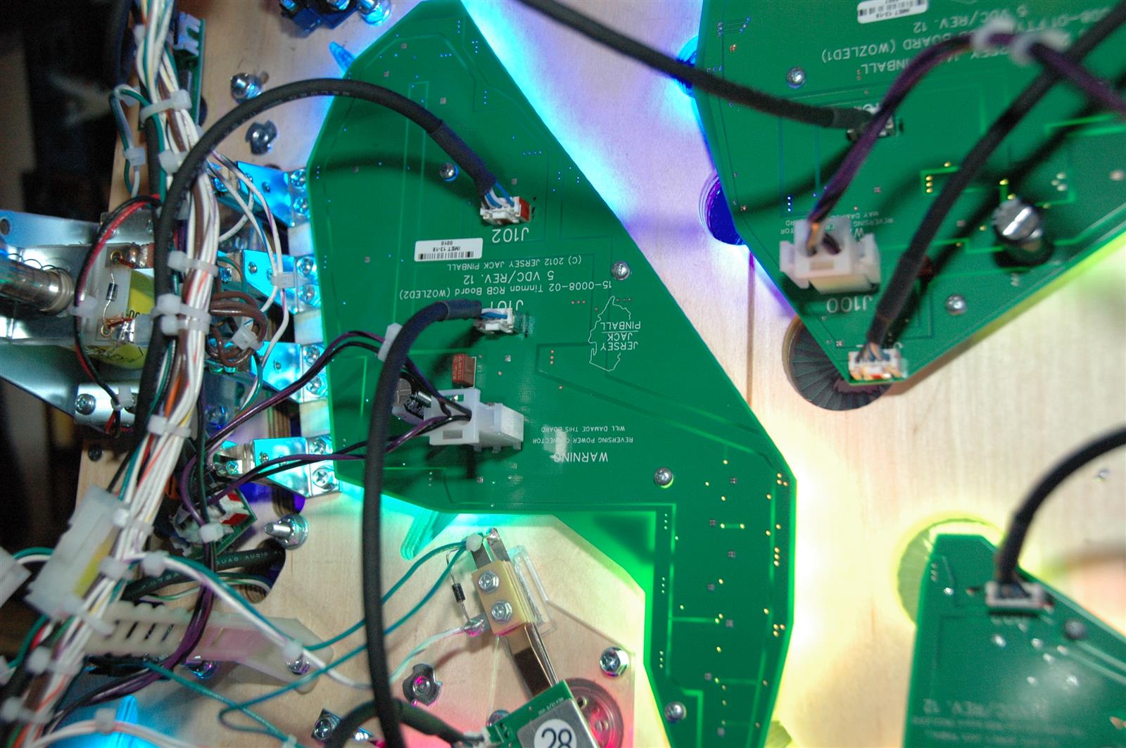 The serial design means that if you lose one board, everything after it loses its data. From what I’ve read, Stern’s color changing LEDs work the same way, so undue criticism shouldn’t be heaped on JJP. I’m afraid this is the way these things are going to work from here on out. Anyone with more knowledge of the system is welcome to give their insight.
If you do have a board go out, you can route around it and get the remaining lamps operational. But the remaining lamps after the bypassed board are going to be off by the number of LEDs that are taken out of the chain. So you’ll get lamps, they just won’t be illuminating the correct inserts.
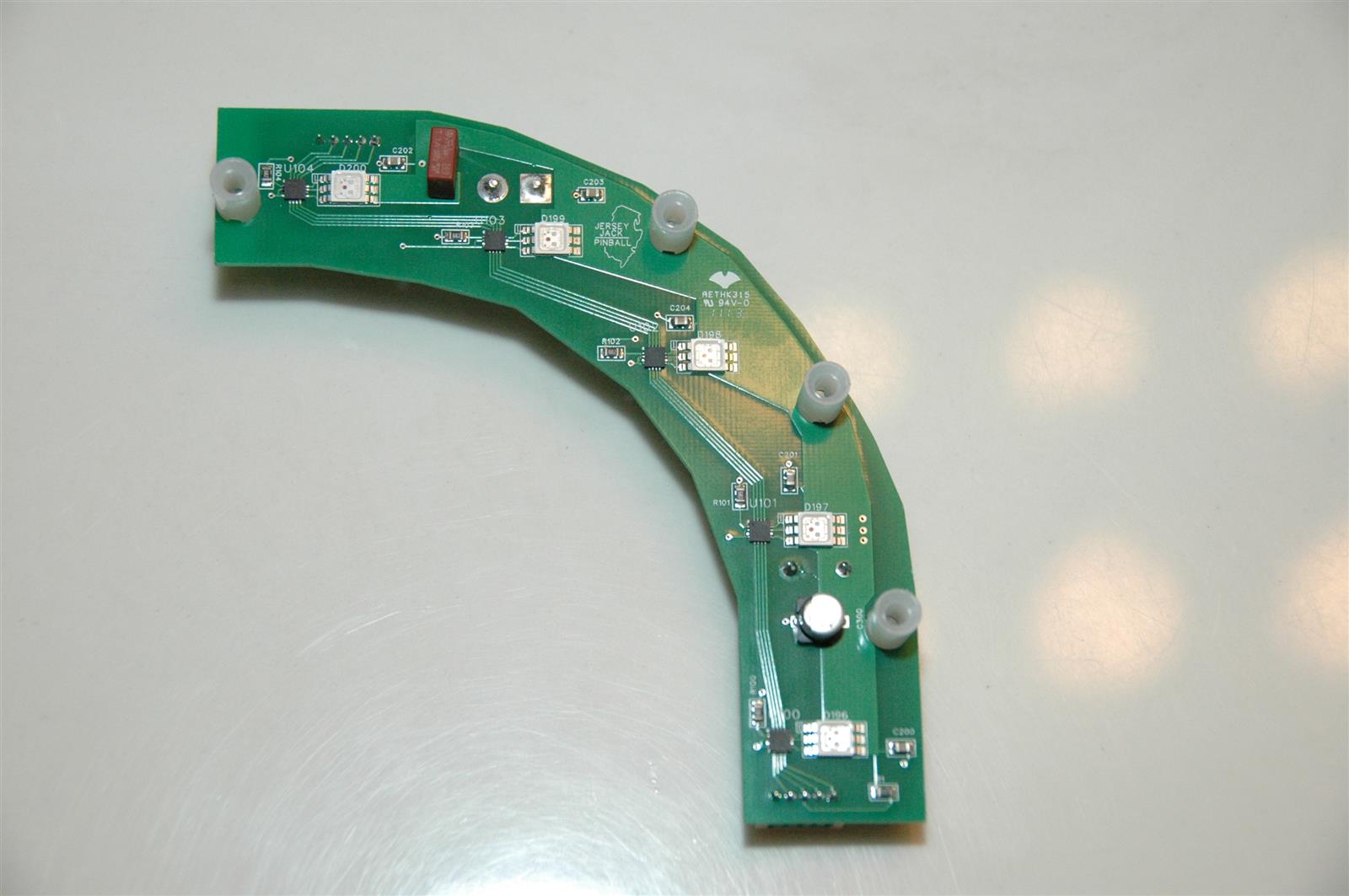
Following are close ups of both sides of one of the lamp boards. In this case, the Follow the Yellow Brick Road board located at the State Fair pop bumper.
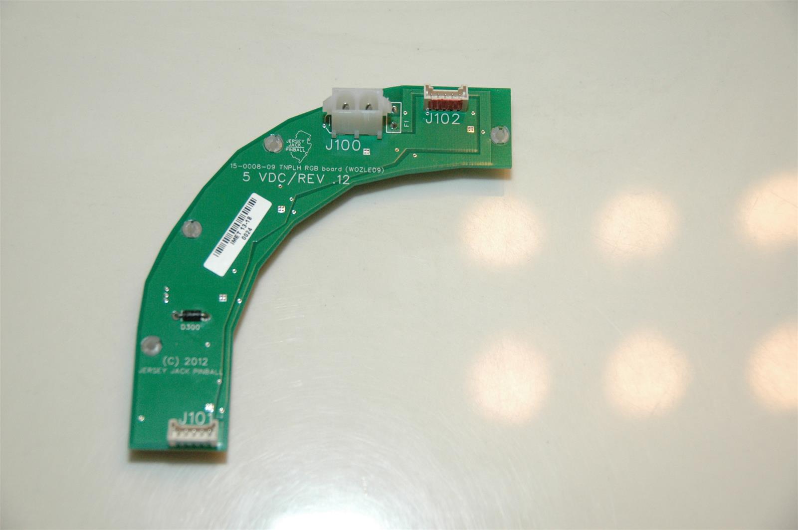
 Here’s a close up of the components on the board:
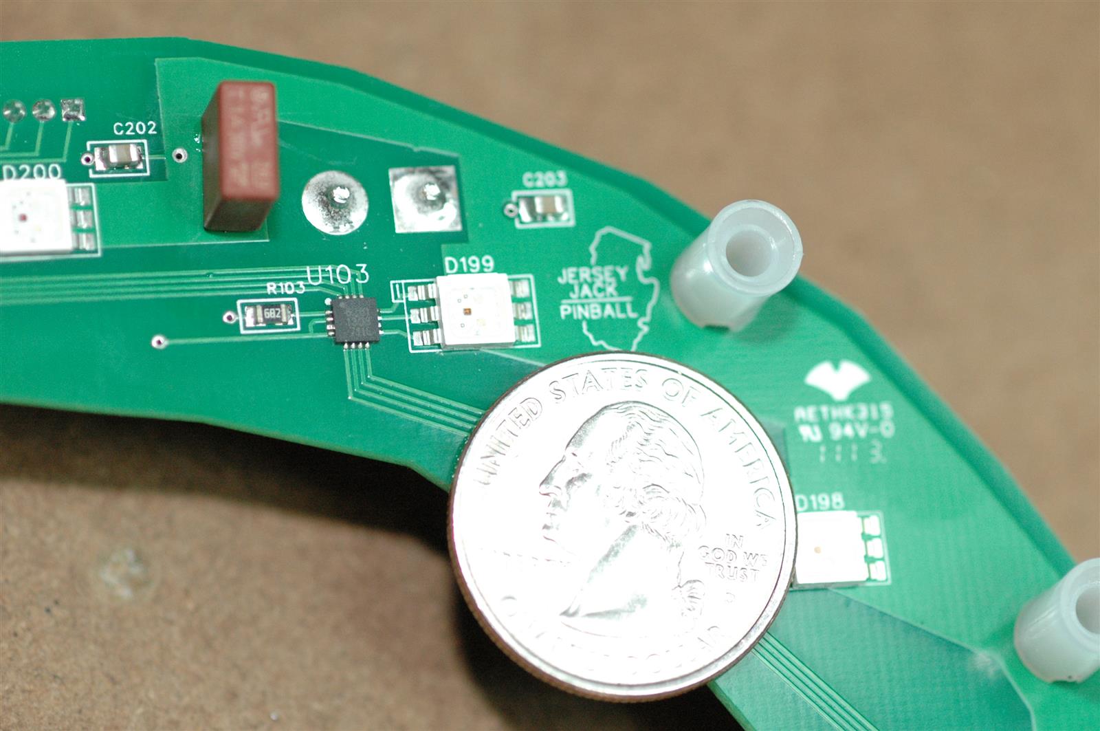 Tiny stuff! The little square chip, U103, is a A6281 3-channel Constant Current LED driver. Google A6281 and you’ll find more information on it. I may update the post later with additional info. but for now we’ll move on to other stuff. The brown part is a 1A slow blow fuse. No quick fuse replacement if that little guy goes out. However, if it does go out your problems probably won’t be fixed with a simple fuse replacement.
Below is one of the GI single RGB LED boards. This is an older revision, the layout of the newer revision is a little different, but it still gives you an idea of the size and what is in the game.
 Below is the underside of the witch assembly. It uses a stepper motor with a threaded rod running through it to raise and lower the witch. There is an opto at the top and bottom of the motor assembly to sense when the witch is at its limits of travel. At the right of the assembly and to the left of LED board is the bash plate assembly for the witch with two microswitches.
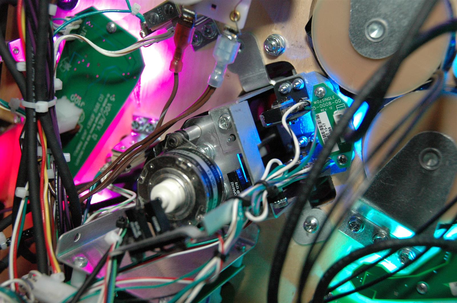
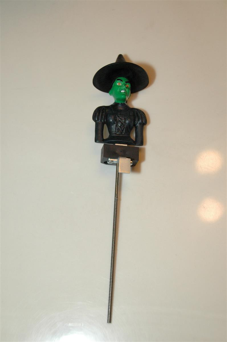
Here is the top assembly for the witch showing the rod and blocking plate for the lower limit opto.
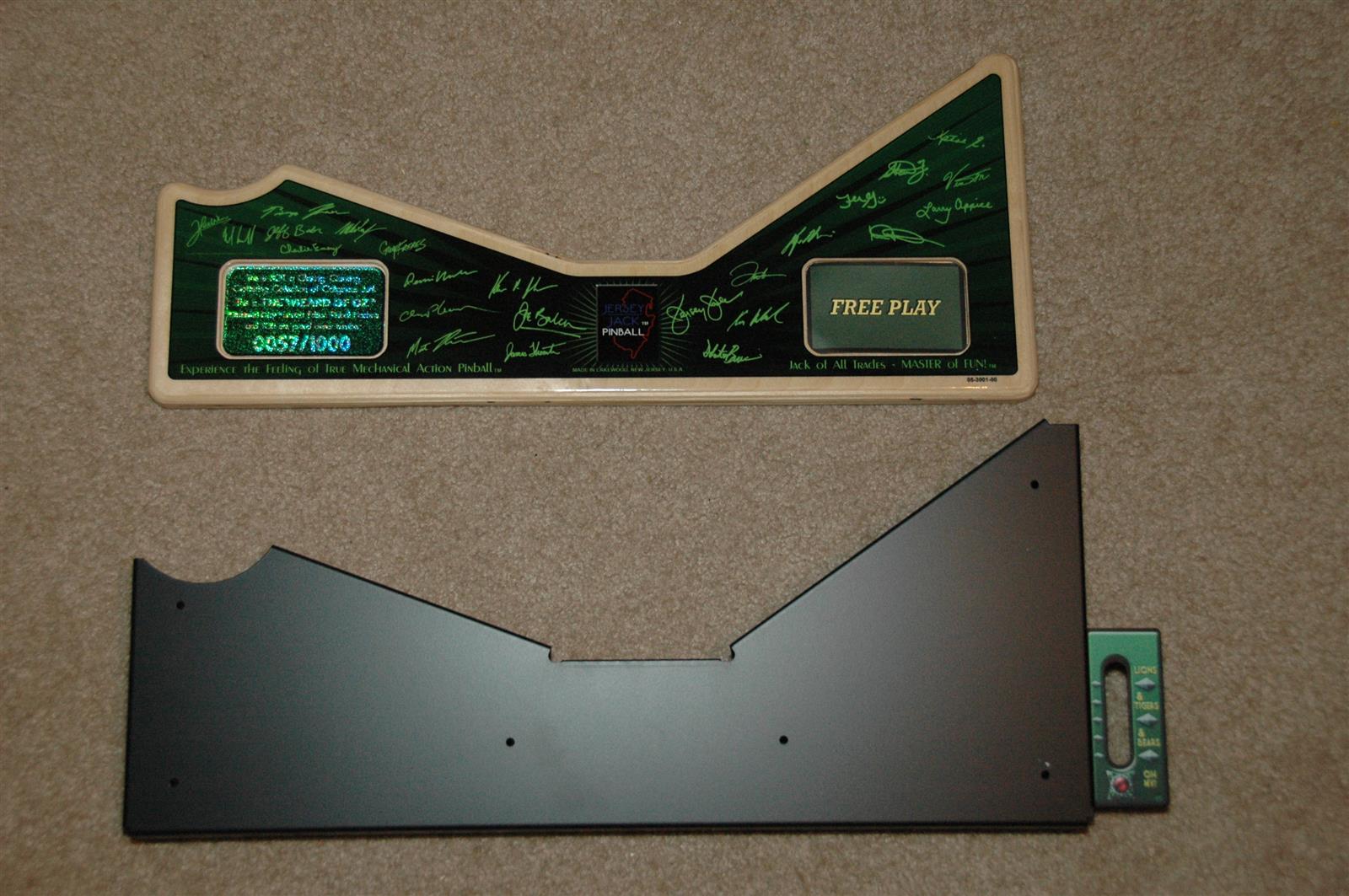
 I ended Part 1 with a bit of a downer, and I’m afraid I’m going to end this one that way too. If you remove the wood apron cover, you are left with a plain black apron. No, there isn’t a decorated apron underneath. Not a big deal to me as I think the design of the topper is well done and looks great. But if you were expecting a regular decorated apron underneath, it isn’t there.
 That’s it for Part 2, but I plan to add to and update the post. In Part 3 I’ll detail the electronics inside the PCB chassis and inside the cabinet.