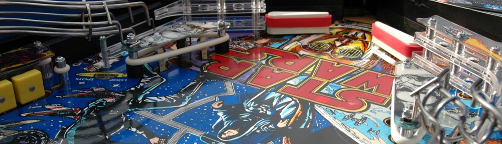
I was repairing a Data East power supply for a client and started off with the typical suspects. Capacitor C2 was clearly no good, it had spilled its electrolyte on the PCB and had to be replaced. This is fairly common because C2 is located right under the large heatsink, and it gets baked to crisp and dries out. C2 in the photo below is shown as an example, it is not the suspect that leaked.

I also replaced a few other capacitors for good measure. After replacing the caps and doing some other housekeeping work, the PS still wasn’t working. So I decided it was then time to check the 2N6057 at TR5. I removed it and came to the realization that someone had either replaced it in the past or had messed with it in some manner. It was either installed incorrectly or the legs were shorted and touching the heatsink. I also noticed that its heatsink was mounted upside down, and a mounting bolt and nut were missing, another giveaway that someone had messed with the board in the past. I reoriented the heatsink and installed the 2N6057 correctly and everything worked.
The weirdness continues but first some background information. Data East made several revisions to their power supplies during their production to support different displays and flipper combinations. One change involved the diodes at D10 and D11 being swapped, and a resistor being added at R17.
In summary, the differences are:
Part number 520-5047-01 Rev A
- Has no resistor R17
- The Zener diode at D10 is a 1N4764 and is tied to ground
- Zener diode D11 is a 1N4743
Part number 520-5047-01 Rev B,C and 520-5047-02
- Has a resistor at R17
- The Zener diode at D10 is a 1N4743
- The Zener diode at D11 is a 1N4764 tied to ground
The power supply I was repairing a Revision B. See the resistor in the middle of the picture? What is that doing there?
")
Look closer below you’ll see that the solder work to attach it to the board is not very well done. Look even closer and you’ll see that the trace underneath it was cut. So what has been done here is to effectively add R17 to the board. I then double checked D10 and D11 and sure enough, they were swapped to effectively make this a Revision C board.
")
I’m not too surprised because I’ve already determined that this board was worked on in the past. Someone must have also modified it to be a Revision C board. Based on how the previous repair was done, I figure I’d better check their work, so I flip the board over.
")
The circled areas are D10 and D11. Click to zoom and take a good look at the solder pads. Maybe I’m crazy, but I don’t think D10 and D11 have been replaced or swapped. Yes, the right side of D11 looks like it was clipped a little differently than the other leads, but there is no sign of damage to the solder mask and the solder itself matches the rest of the board in appearance and tarnishing. The rest of the leads are bent and clipped like every other factory lead. I really think this board came modified from the factory to be a Revision C board. Weird.